Saturday, August 4, 2018

 ANK LABS 
  
LOGIC GATES

Hello friends today in this Post I will explain each and every functions in Boolean control palette. if we compare functions in Boolean palette with logic gates there are same, That means we can perform all operations with can be done with logic gates well logic gates can be used for binary addition, binary subtraction and much more.
After finishing our tutorial I will give some example task for you. If you find difficult I will explain later in my upcoming video you can easily finish the task if you understand carefully. Have fun.

In this tutorial we will be covering the following functions under Boolean palette.
Add caption


Let’s get started:
AND gate
The AND gate gives a high output (1) only if all its inputs are high.  A dot (.) is used to show the AND operation you can consider the same as A.B but it’s should be denoted as AB.


OR gate
   The OR gate is an electronic circuit that gives a high output (1) if one or more of its inputs are high.  A plus (+) is used to show the OR operation. It’s just simple as adding  (0 and 1).but of course 1+1 is not 2 in this case logic's can have only two values either high that is (1) or low that is (0)


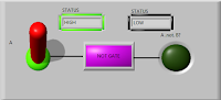
NOT gate

                The NOT gate produces an inverted version of the input at its output. They are also called as inverters. If the given input is HIGH the corresponding output will be LOW.


NAND gate
                This is a NAND gate which is equal to an AND gate followed by a NOT gate. The outputs of all NAND gates are high if any of the inputs are low. If you see this image its similar to an AND gate but has a circle at the output this small circle is called the inversion.

The output of NAND gate is the same as AND gate but the output is inverted


NOR gate
                This is a NOR gate which is equal to an OR gate followed by a NOT gate. The outputs of all NOR gates are LOW if any of the inputs are HIGH. If you see this image its similar to an OR gate but has a circle at the output this small circle is called the inversion.


EX-OR gate


The EX-OR gate which is 'Exclusive-OR' gate give a high output if either, but not both, of its two input are high. The EX-OR gate is denoted by an encircled plus sign .


EX-NOR gate

   The EX-NOR gate which is 'Exclusive-NOR' gate which give a low output if either, but not both, of its two inputs are high.


The NAND and NOR gates are called universal gates because they can perform the operations of all basic logic gates such as AND, OR and NOT gates.

This simulation can also be done in labVIEW . The programs which you create in labVIEW can also be used as standalone application. labVIEW run time engine help us to use them without labview software.

What will you do if someone ask you to realize the logic gate using IC’s, well you can perform all that you want using the logic gate IC’s I would have made a separate post on that due to time shortage and it’s a boring topic so I quit. But I can do one thing I can teach how to use wire them.
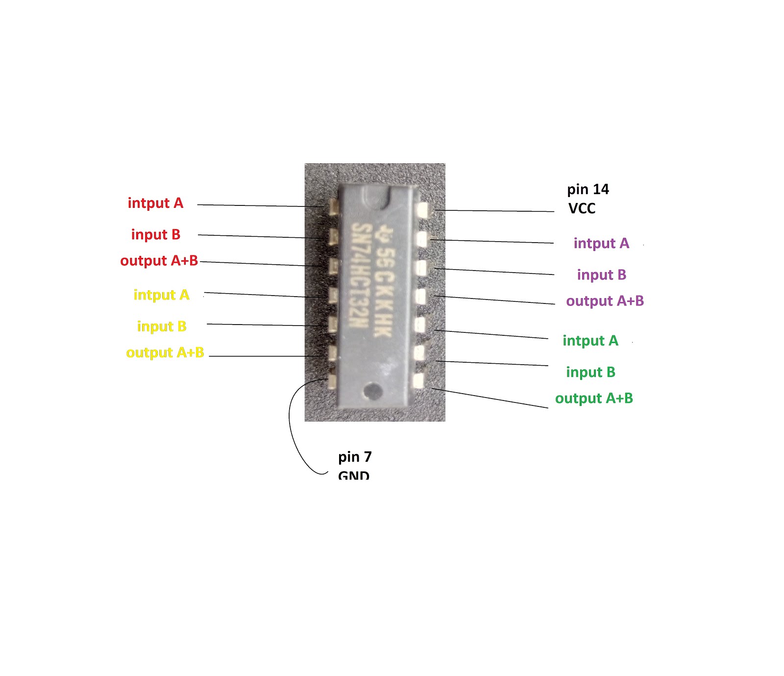
Download data sheet for more details.

AND gate

3 input AND gate

OR gate

NOT gate

NOR gate

IMAGE NOT AVAILABLE

NAND gate

EX-OR gate


This tutorial ends here the same content will be uploaded in my youtube channel so don’t Forget to like share and subscribe.

 Follow my blog for more updates.

LabView task:
1 - HALF ADDER USING LABVIEW BOOLEAN 
     DATA TYPE.
2 - FULL ADDER USING LABVIEW BOOLEAN 
     DATA TYPE.                          
3 - RS FLIP-FLOP USING LABVIEW BOOLEAN 
     DATA TYPE.
4 - JK FLIP-FLOP USING LABVIEW BOOLEAN 
      DATA TYPE.
5 - GLOW FIVE LED'S WITH DIFFERENT COLOR 
      USE ONE BOOLEAN CONTROL.

labVIEW logic gate Simulation
Don’t forget to use my simulation programs.

AND GATE


OR GATE


NOT GATE


EXCLUSIVE-OR GATE


NOT EXCLUSIVE-OR GATE


NOR GATE


NAND GATE


DOWNLOAD .vi file


DOWNLOAD .vi file (SIMULATION)


What’s next?

          In my next blog/youtube video I will explain the functions of numeric control palette. Before that we will finish out 5 task under Boolean data types. This task will be explained in my youtube channel “ANK LABS”.

Saturday, July 7, 2018


RESISTOR
                  

  Hello friends, today in this article I will explain what is resistor and how to use them in your circuits and we will also discuss about the Resistive loads and some practical examples which we use them in our day today life.

Resistor are used everywhere starting form the small circuits to integrated circuits like IC’s even our computers processor has thousands of resistors. Even the wire which we use for connection purpose has resistance of 0.001 ohms its actually depends on the length and the radius of the wire but super conductors there are special they have zero resistance under suitable conditions.


What is a resistor?
           The word resistor means it resist something ,i.e not allowing to pass through or blocking the passage. In electronics its used to limit the current. Resistor is a current limiting device.it has two terminals, it limits the flow of current by dissipating excess energy in the form of heat. They are often use in electronics for current limiting, Transistor biasing, feedback loops, potential divider etc.

This is the image of a virtual resistor.


Various types of resistor which I have collected so far

 Making your own resistor (DIY resistor):
                   Friends we can make our own resistor by simply wounding a copper string or any other type of conductor over a non-conducting core (insulator). I have tried to make on but finally I found it’s a total waste of time. It’s better to buy a new one.

  DIY (do it yourself) resistors have several disadvantage.
     It consumes our precious time. (1 kilo ohm resistor would requires nearly 100-1000 turns or more depending up on the wires diameter and conductivity of the material)
     By making one DIY resistor you are not gone save money. Material cost will be much        
higher than actual resistor.(In India 1 resistor is lesser than 1 rupees).
But you can make resistors with 10-30 ohm with high wattage (10-50).

I had a 2.2ohm 10 watt resistor when I break it I got this


The broken one consist of 14 windings of conducting wire, conductor type and diameter of wire is very important while designing a resistor. You can use old stuff to make resistor of your own for high watt resistor you need a conductor which has large diameter but for that u have to wind 50 turns.
This DIY resistor is only recommended in case u cannot get certain wattage resistor in your local 
shop. Know a day’s you can get all you want through online stores. At low cost.

Types of load:

Loads are broadly classified into inductive load, capacitive load, last but not the least resistive load. 
Today our topic is resistor so lest see what is resistive load.

Resistive load:

Know a day’s resistive loads are not used because of its poor efficiency. Resistive loads just consist of a resistor. If you are not familiar with a resistive load here some example which shows what are the 
resistive load which we use in our house.

Example 1:
Light bulb

 We are familiar with a light bulb and where it is used but have you ever imagined how efficient it is. Well I will show how efficient they are before that lets have a look at the old style light bulb.


It this type of light bulb electricity is made to flow through the thin wire which is called the filament.


When current flows through the resistor energy is dissipated in the form of heat. When a metal becomes hot its start to glow.


This principle is used in this electric bulb but another question arises when metals like iron, silver, Gold will melt at high temperature. Because this drawback they use tungsten material because they can handle high temperature without melting. This thin wire are protected under a glass shell in order to protect the filament and to prevent it from reacting with air. Generally they are less reactive when compared with copper and other metals.

Example 2:
          Old style water heater, iron box hair dryer etc. Still most of the iron box uses the same principle. They use Nichrome wire as heating element.


this contains nichrome wire which gets hot and so hot air comes out of it.

Nichrome wire are unique they have high resistance when compared to other metals. This image shows the resistance of a Nichrome wire of 1 meter length. (1 meter = 100 cm).


If you want to check the resistance of any conducting wire use your multimeter and adjust it for measuring resistance. As shown in this image.

Example 3:
     If you really love electronics you might have some soldering irons lying around I got three of them and tried to make one DIY soldering iron. Look at this image. My DIY soldering iron is not good but its works.


Even this irons uses nichrome wire.

How to use a resistor?

 As we know resistor is used to limit current. If I want to add a current limiting resistor to a led circuit. Then I have to do some calculations for inserting a proper resistor if your resistor value is too high then your led will not glow sometime it will glow dim. Similarly when resistor value is low then   led will be destroyed.

I had a 1 watt led which is operated at

V = 3.6 volt (led voltage)

 Power = 1 watt


We know voltage and power consumption of this led, but still current value is unknown let’s make use of ohms law to determine the current consumption of the SMD led.

Current    I = power/volt
              
                  = 1/3.6
              
                  = 0.2777 Amp

To determine the resistance which to be added when the supply (source is 5 volt)

5 V (power source) – 3.6 V (led voltage) = 1.4 V

1.4 volt is the excess voltage which we have to remove by adding suitable resistor.

Using ohms law

                  V=I*R

Where,
             
                        V = excess voltage (1.4 volt according our problem)
          
                         I = led current (0.277 Amp)
            
                       R = unknown

Let’s get started

              V = I*R
         
            1.4 = 0.277(This flows through the resistor)*R
          
              R = V/I = 1.4/0.277
                    
                  = 5.05 ohms

This 5 ohm resistor will remove the excess 1.4 volt which is not required but actually they limit the current but due to the proportionality voltage reduces.

Note: standard resistor can handle load of around 0.25 watt but our led is 1watt. Or simply we must use a resistor which can allow 0.277 amps to pass through standard resistors can only allow 0.25 amps its recommended to go for 1 watt resistor or even higher.

Resistance of a resistor depended on colour code.


When you see a resistor they have some ribbons with different colour. Each colour determined its resistance value if we know the colour chat of the resistor then it will be easy for us to determine the resistance of a given resister

Schematic of a simple led circuit is given.


Here is the bread board circuit

In this image I used a white led with proper resistor. Similarly we can design resistor for our circuits.

In this above images I have used some other components like led, regulator, Push button. I will make a separate blog/video to explain they basic operating principle.

In my breadboard circuit I used a 5 volt regulator to regulate the output voltage to 5 volt which is obtained from 9 volt battery. 5 ohm resistor is not a standard resistor so I used two 10 ohm resistor in parallel ( In many cases we much use standard resistors because resistors like 8.2 ohm,69 kilo ohms are possible so we have to buy approximate standard resistor)
 In future I will explain the series and parallel connection of resistors, capacitor, inductors, power supply batteries etc.


First you must learn to how to calculate the resistance of a resistor from the resistor colour code that information is not available here but my youtube video will help you to understand this stay cool I will explain everything in my youtube video.
So friends I hope my blog was useful keep supporting me so I can make awesome videos/blog post for you.

What’s next?
  In my next blog I will explain what is a capacitor, workings, and there applications in practical circuits.


DOWNLOAD SIMULATION FILE


Watch my youtube channel ”ANK LABS”


you can learn the basic of electronics and there components, labview software, some awesome electronic project .additionally I will upload some videos some the internships and implant training which I have attended so far.